
In General
Pictures
The Subway Car
The Riding Car
Floobydust
RAILFAN GUIDES HOME
RAILROAD SIGNALS HOME
A lot of us are into the Live Steam and/or Live Diesel hobby these days, but having something to run is still a luxury for many of us, and not all of us can afford to go out and spend 15 grand (or more) on a locomotive. I'm one of those, but not because I can't afford to spend that much on one engine - I just have too many other hobbies begging for my attention in addition to rehabbing a house. :-)
So.
For a long time, I've wanted something to run. I don't think I wanted to do steam - because I am lazy, and I know I would not have the patience to fire one up, and then clean up afterwards, much less having the patience to build one, so steam was out. Gas would be OK, as they start around $5K...... But that was still too much for me when you have a number of expensive hobbies (ham radio, electronics, you get the drift).
So, what to do?..... Since I've decided buying one is out, I decided to roll my own (we'll see if that is a good choice :-).
However, we're back to the lazy problem compounded by time issues, trying to fit in the construction of this with daughters, grand-daughters, working on a rental property, mowing the lawn, and most lately, being retired (and for anyone who thinks you have MORE time when you retired, you are severely misinformed, just you wait! Why does life have to be so complicated?
My next question, what do I build, and how simple can I make it?
I could do a gas or electric powered steam engine, but that's sort of like blasphemy. I could do a small gas engine powered thing, either mechanical drive, or hydraulic drive, or even a gas-electric, or, I could also do straight electric. So let's do electric, because electric "stuff" is right up my alley having been into electronic and electrical stuff all my life (like radar systems and fixing light rail vehicles). We are also into the ham radio and computer thing too.....
So, since I don't do normal things, we have decided to make a New York City subway car, known as an R-33. Why? I grew up with them during the summers when we stayed with our grandparents, who lived a block away from the 69th St/Fisk Avenue stop on the #7 IRT line in Jackson Heights/Woodside area of the Queens.
Models of the R-33
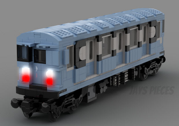
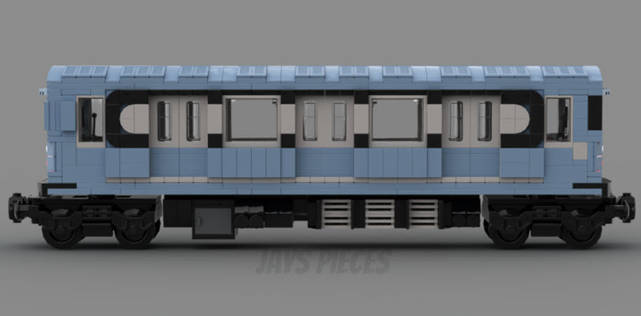
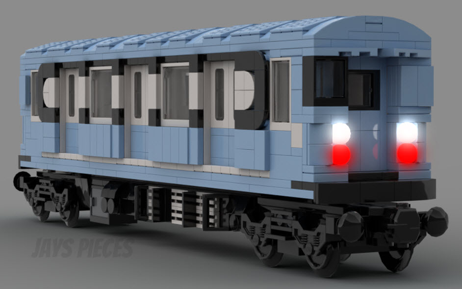
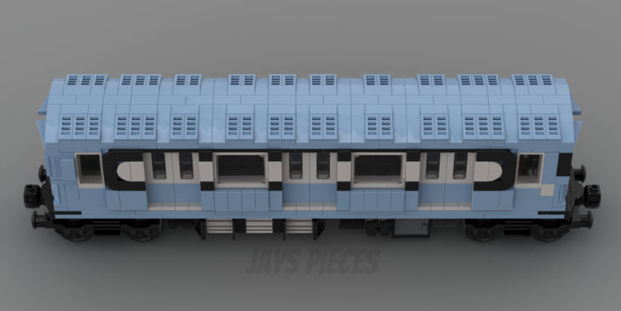
I have several MTH O-scale sets of the R-33's: A four car set of the original Blue Birds, a four car set of the Red Birds, and a two car set of the yellow MOW cars. And I just came across the other day "Lego" version of them (but not made by Lego).
 MTH 30-20354-3 M.T.A. R-33-S Subway (Red Bird)
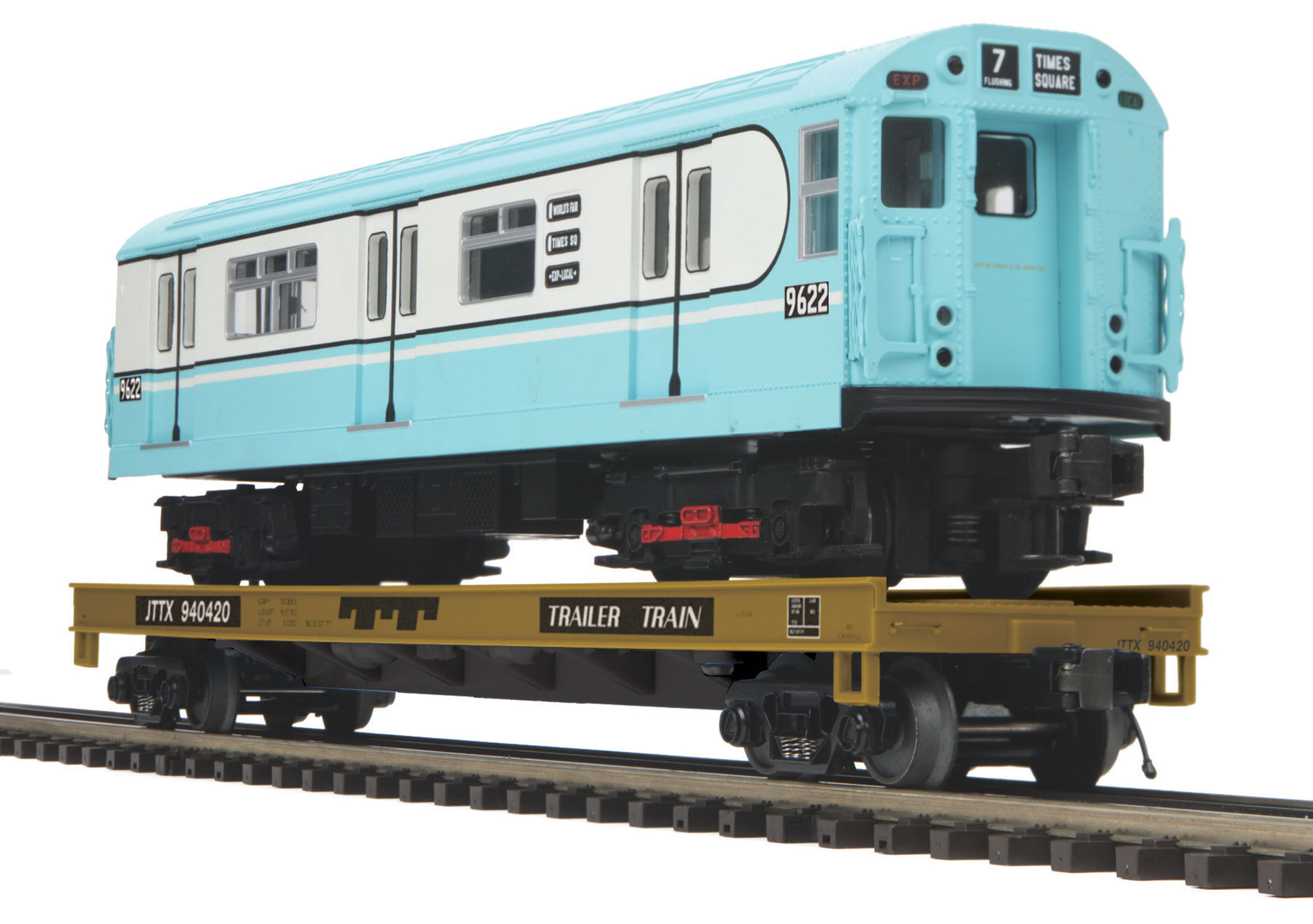 MTH 20-95180
The "Lego" version is offered by RE BRICKABLE. The kit number is MOC-168004 and contains 1160 pieces. However, Rebrickable does not sell a kit, they only sells the plans - so you have to go out and buy your own parts, which isn't too hard to do on Lego's website.
I may also try to build another "33" while this subway car is taking place, and that is the New Haven E-33. Convenient that they both have the 33 in there "type" number, and that the two used to cross each other at 69th St and Roosevelt Ave in Jackson Heights, feet from where I used to spend my summers at my grandparents.
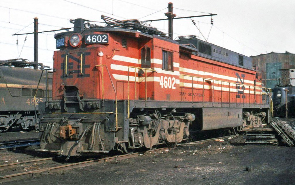
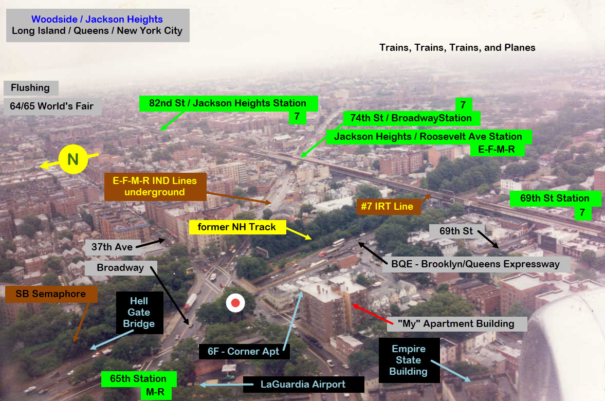
This is where I grew up in the 50's and 60's during the summers. What a great place to watch the world go by, and you can also understand why these guys are my favorite "electrical" trains! :-) :-) You had the New Haven running by on their way to Hell Gate Bridge, the underground IND lines a block away, and the elevated #7 IRT line a block away in the opposite direction - plus, you could watch planes landing at LaGuardia Airport (which is how I snapped off this shot when landing there). You also had a ringside seat of the planes landing at LaGuardia when they got stacked up, and with a pair of binoculars, you could watch them drop down in the levels - that was pretty cool!!!
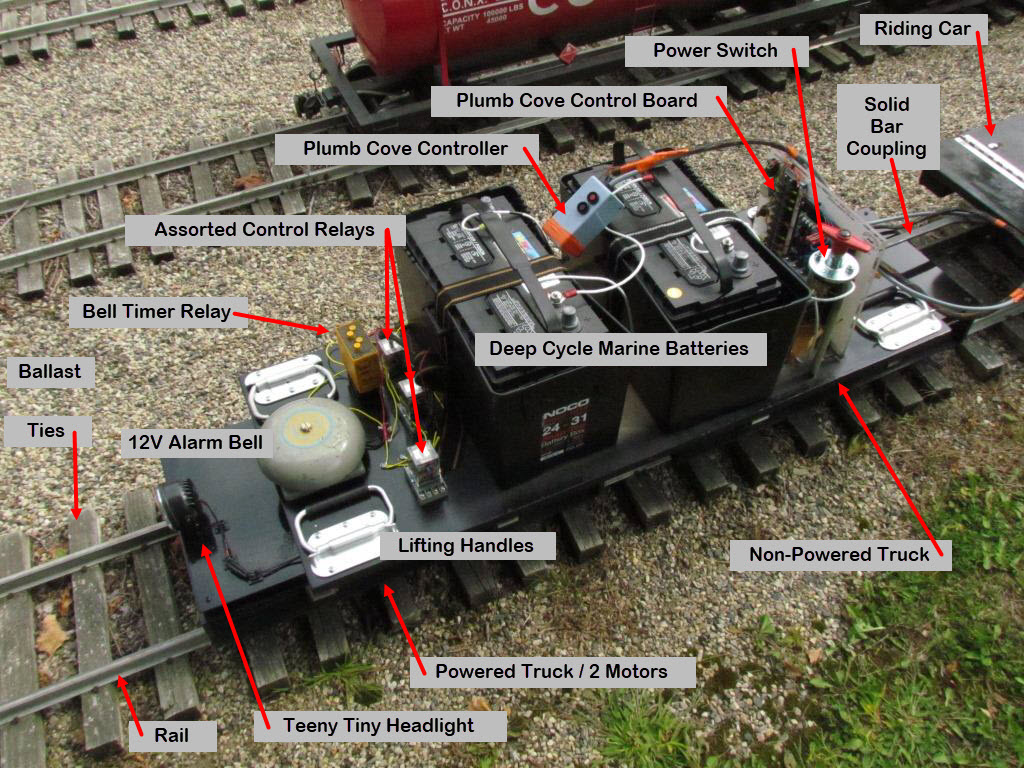
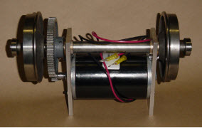
The next picture is of the proof-of-performance thing I built, last seen at White Creek in 2014. It only hauled around a two-person riding car, so the two motor truck handled the task with ease. There's no brakes except for regenerative braking.
A few sources of info:
http://www.4qd.co.uk/ Manufacturer of DC power control systems, up to 84V
https://pikerivernorthern.com/ Supplier of trucks and wheelsets - powered and non-powered, wheels, axles, and motors
https://gardei.com/IPRR/ Columbia RR, formerly the Island Pond Railroad, Columbia TN - lots of help to building your own backyard railroad
http://www.plumcovestudios.com/ Supplier of trucks & wheelsets - powered and non-powered, wheels, motors, axles, 24VDC controllers, and Generic Electric loco
https://en.wikipedia.org/wiki/R33
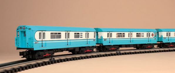
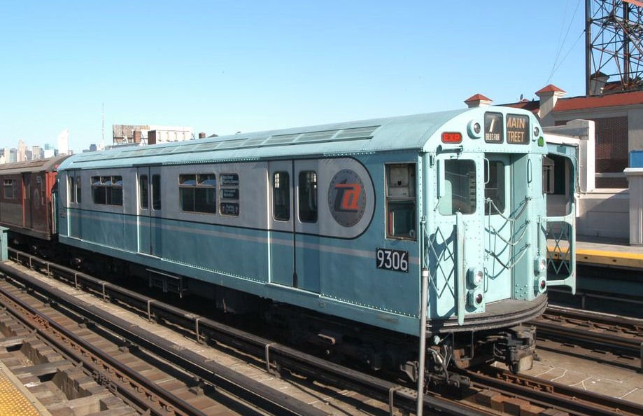
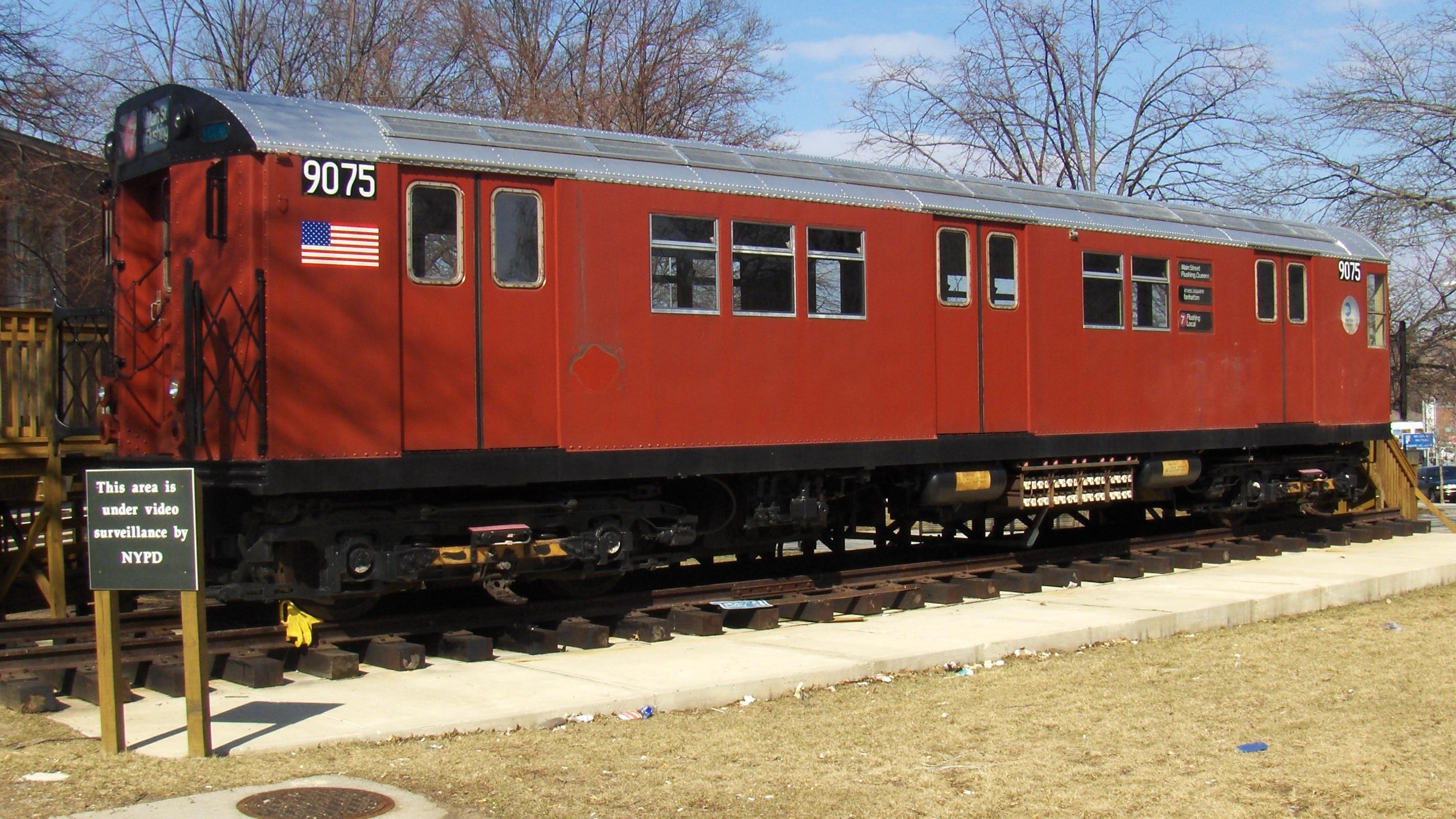
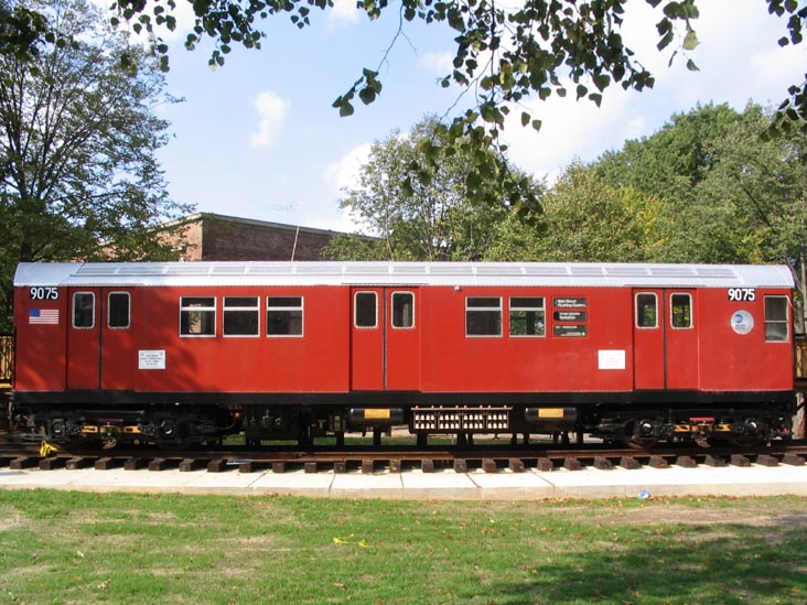
The picture below is of the classic New York City Transit Authority Worlds Fair subway car, nicknamed "Blue Birds". The R-33 cars were built in 1962 and 1963, 500 were delivered. The cars were designed to be operated as a married pair, not because the two shared equipment, but rather, the cars only had one operators cab in each car. Now, if you are familiar with the number 7 line, you know that most of the platforms had room for 11 cars. So a number of the 500 cars delivered had cabs at both ends, not sure of the exact number. This is the style I am going to build. Not sure why they didn't just design a way to put three in a set, and disable the cab in the center car.... The Wikipedia article does not mention or discuss the double cab cars at all.
What is now the MTA, back in the 60's was known as the NYCTA, or TA for short.
In later years, they picked a Pennsy colored red to paint the cars, and they became known as the "Red Birds". The blue painted ones famously served The Worlds Fair in Flushing, Queens, during 1964-1965. Most of us "old-timers" should be familiar with the fair, as two of the (still) standing towers at the end of the first Men In Black movie were at the fair's site.
Back Story: My grandparents lived about ten stops away from the World's Fair on the #7 line, so I was already used to being on these things all the time. My favorite thing to do: was to spend the day riding the subway, and standing in the front window (next to the operator) watching everything. Too bad we didn't have the cellphones like we have today, I'd have some great pictures and video!
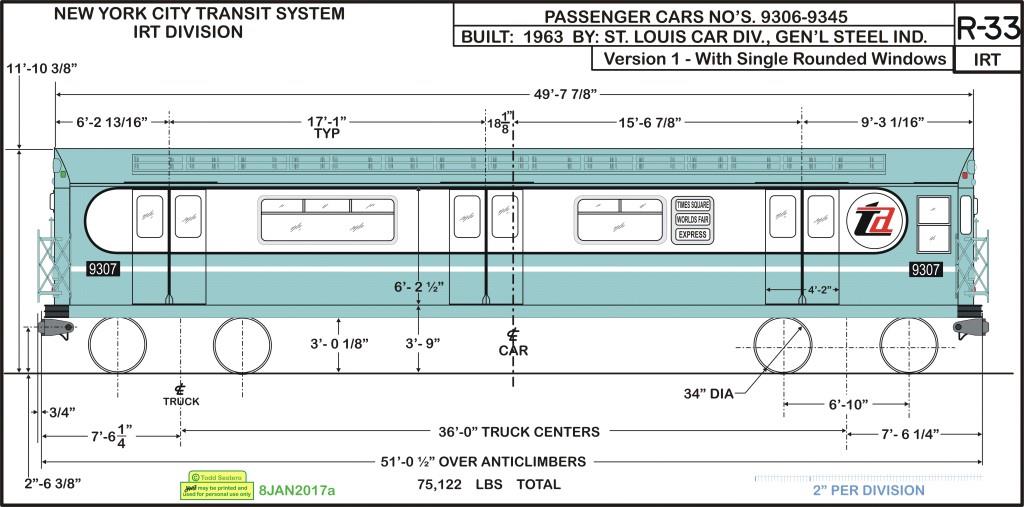
My version of the drawing below
The picture below is the highest def picture I have come across to date. All three pictures below were taken at the Queensboro Hall. Ahhh, the good ole days when you could go between cars and stand at the window and watch everything coming at you. Great entertainment when I was a kid for 15 cents to ride them ALL DAY LONG! You never had to come out into the sunlight for anything, for, if you knew where they were, there were plenty of places to get lunch underground!

Scale
A Quick Once Over
the Motors
the Trucks
the Controller
the Frame
the Body
Doors
the Couplers
Electrical - Low Voltage Section
Electrical - High Voltage Section
the Air and Vacuum Systems
Brakes
Other Stuff
Scale
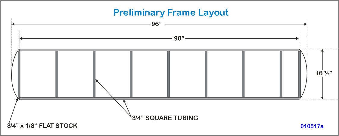
In order to make the car about the same width as most 1/8 scale cars, I'm going to use a scale of 1:1.9. This makes the 51 foot long car 97" long in scale, so we'll round it off to 8' even, or 96". At the same time, this would make the 8'-8" wide car a scale 16.5" wide. While the scale is greater than the standard of 1.5 or 1.6, it still shouldn't look too out of place because of the width.
A Quick Once Over
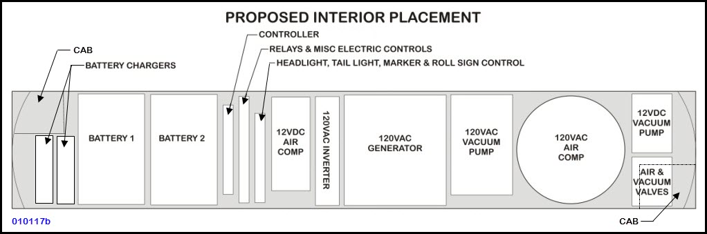
On the inside of the subway car, there will be "a bunch of stuff!"
Although the order of things and what is going in has changed slightly from my first layout, I'm planning on including:
-- Two full size Deep Cycle Marine type batteries over the front truck
-- The controller, mounted to one of the aluminum plates/mounts
-- Two or three two aluminum "L" plates/mounts for electrical and pneumatic controls
-- Two battery chargers, possibly mounted to one of the aluminum plates
-- Air and vacuum valves, mounted to the aluminum plates
-- A 12VDC vacuum pump
-- A 12VDC air compressor
-- A 120VAC vacuum pump
-- A 120VAC air compressor
-- A 120VAC generator
-- A 12VDC to 120VAC inverter
The two pumps, air compressors, and DC to AC inverter provide a system of back-ups.
The vacuum reservoir tanks will probably go underneath the car.
We changed things around so that we -could- include a detailed operators cab.
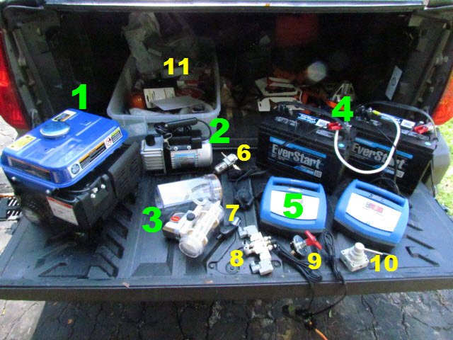
Most of the stuff that will be going into the subway car:
1) The Harbor Freight 800w generator
2) The HF vacuum pump (120VAC)
3) The Laerdal vacuum pump (12VDC)
4) The two deep cycle marine deep cycle batteries
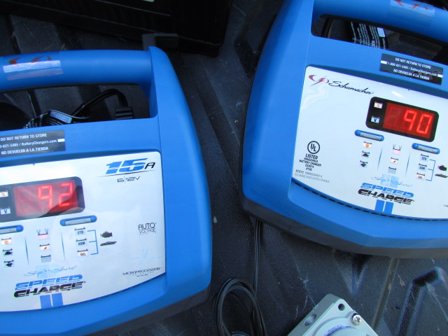
5) The two Schumaker 15A battery chargers (changed, we're going to get something smaller)
6) Combo air pressure regulator and water separator
7) 6 pin plug and receptacle
8) An electro-pneumatic 5x2 air valve
9) Battery cut-off switch
10) The main brake control valve
11) Box full of the other parts I will be needing.
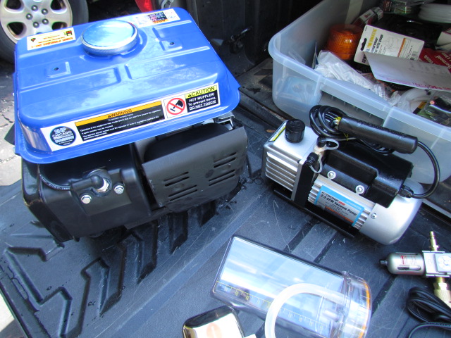
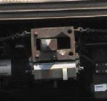
The Harbor Freight generator and vacuum pump
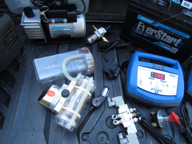
The two vacuum pumps, battery charger, and misc electrical and pneumatic "things".
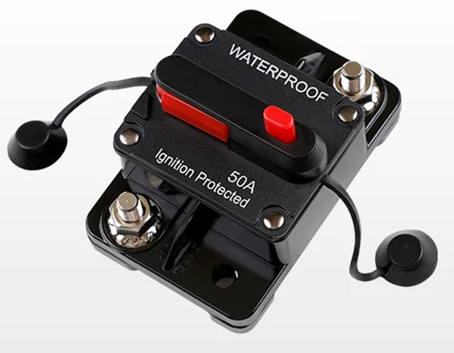
Probably going to replace the switch shown above with two of these - 50A circuit breakers/switches
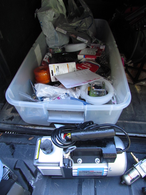
The vacuum pump and tray with other stuff needed for the project.
the Motors
I'm planning on using "scooter" type motors, maybe Plum Cove, maybe not. They want $450 for one powered axle, $100 for just a motor, and $80 for an axle. I think I could make and find the rest of the parts for less than $270. Maybe not :-) BTW, Pike River Northern sells a powered axle for $500, so I guess $450 isn't too bad.
Scooter type motors would be able to be hung down in between the axles. Larger type scooter motors would have to be mounted above the trucks, taking up precious room inside the car.
I'm planning on having all four axle's powered.
If I get really ambitious, I may also power the four axles of the riding car, then we should have a real "puller"! :-) The two full size marine batteries should have no problem powering 8 motors.
Two powered axles, each with a 24 volt motor hung on the axle, would be approximately half a horse with a 6:1 ratio to the axle if I use the same ratio as Plum Cove as used.
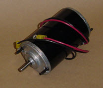 the Plum Cove powered axle and motor.
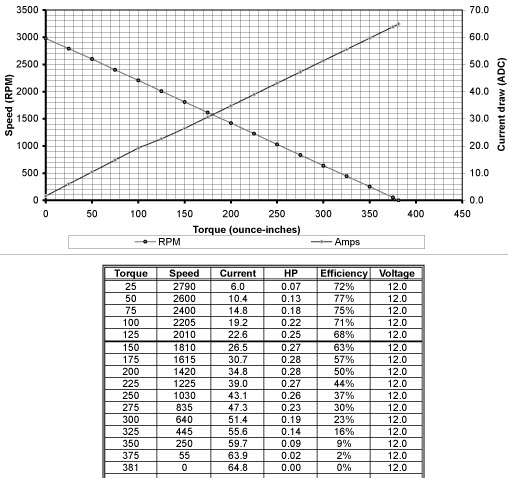 Electrical data for the Plum Cove motors, others should be similar.
the Trucks
Initially, I was planning on using a Plum Cove truck as is, but they are too large, and don't look right. It's probably easier to roll my own.
I'm thinking of welding a frame together using square tubing, and then adding a decorative face to the outside, to approximate the look of the subway trucks.
To mount the trucks to the frame, I'm planning on using a bolster beam across the truck, and mounting one of those things used on boats that allow a boat seat to rotate. It's a heavy duty Lazy Susan type bearing. On the bottom side of it, I plan on putting small compressible springs to allow the truck to move slightly in the other two axis' so the subway car doesn't derail when it goes over "bumps in the road". I think they were $10 each. Note: since the axles are already sprung, I may not need to use the springs for additional movement.
The arrangement with the lazy Susan's and extra springs has proven to be a successful idea after running another electric powered engine around the White Creek for two days, so I may use it again!
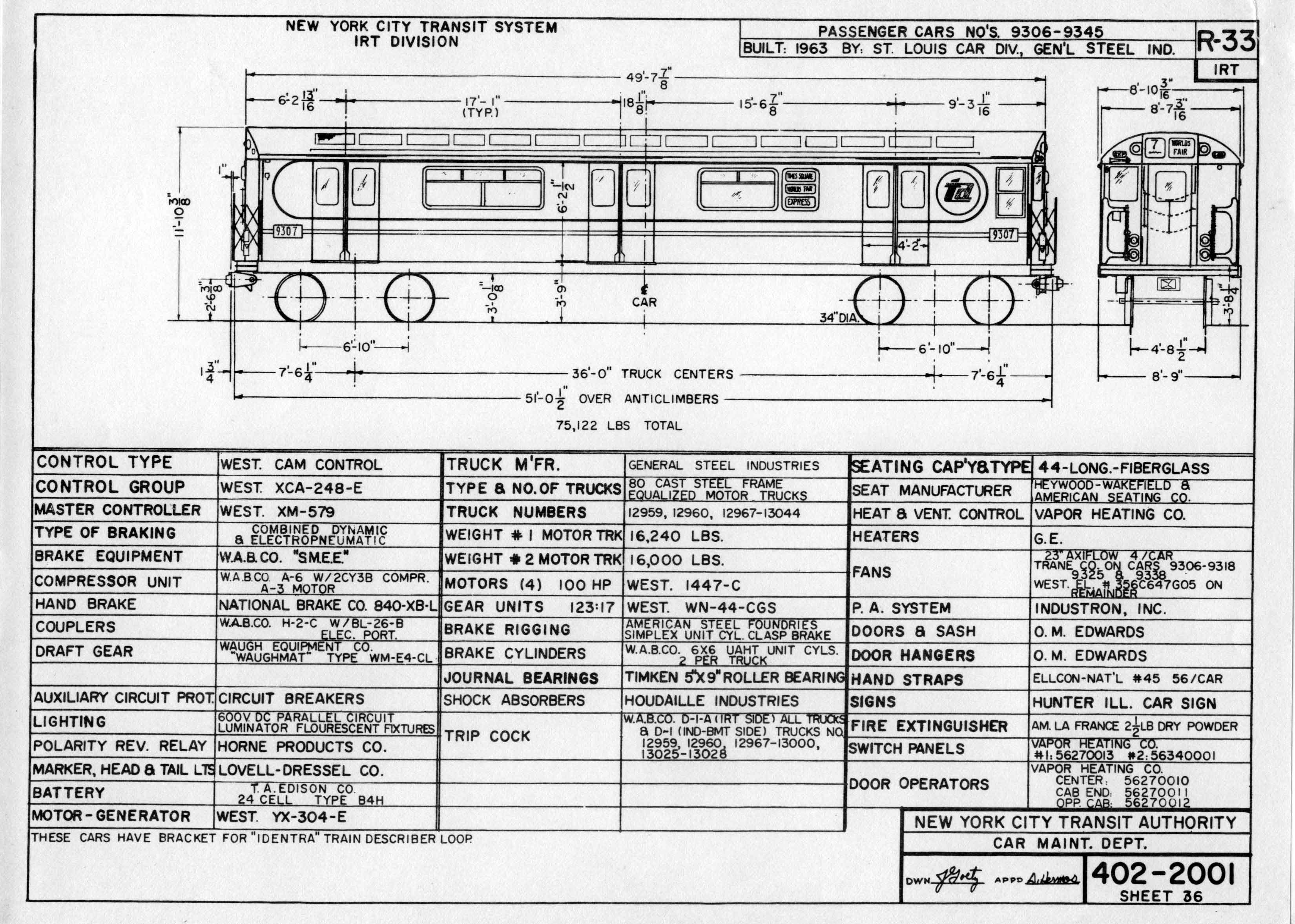
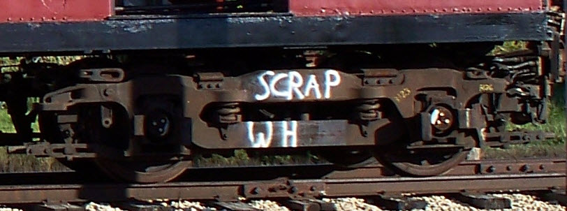
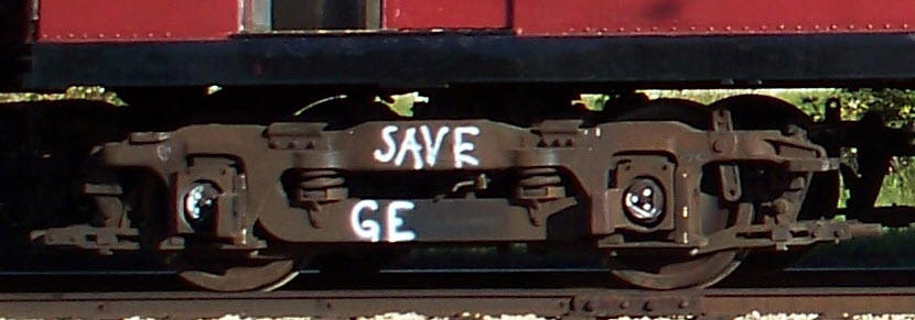
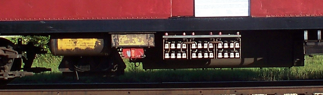
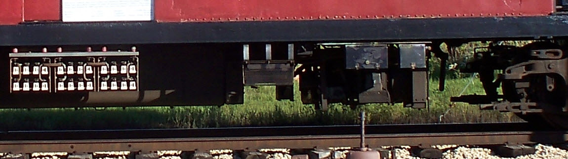
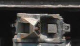
The pictures below are screen shots from a side view of the car, with sufficient resolution to blow up enough to see some of the details - it also does not have the third rail pickup shoe and support on the truck to get in the way! I included the door opening in the shot, so you can get an idea of the scale - the opening is 4'-2". To explain the markings on the trucks, electrical equipment on the 33 series was made by two manufacturers: Westinghouse and GE. The equipment was similar, and probably derived from the same set of drawings and/or specifications (an assumption).
the Controller
Again, I was originally going to go with Plum Cove's controller - they offer what was previously sold by Diverse Electronic Services.
However...... I feel the power handling capability is too limited, so I think I'm going to use a 4QD DNO-10 controller. It will handle a continuous current of 100 amps at 24V, the Plum Cove controllers are only rated for 35 amps continuous.
The 6 pin connectors will be "strapped" so that depending on which end the hand controller is plugged into, the end facing you on the riding car will always be "the rear" for direction purposes. This means it doesn't matter which way you put the thing on the track. Nice thing about them thar transit cars, huh? We accomplish by using a hi-current DPDT (double-pole, double-throw) relay, which will swap the controller output leads.
The output of the controller will also be used to control which end the headlights light up on, another simple task with electronics :-). All you have to do is sense the polaity of either output....
I would also like to put an R/C control in it too, that would be cool. If I do that, I bought a flashing yellow light to put on top of the subway car so people know it's moving by itself! :-) :-)
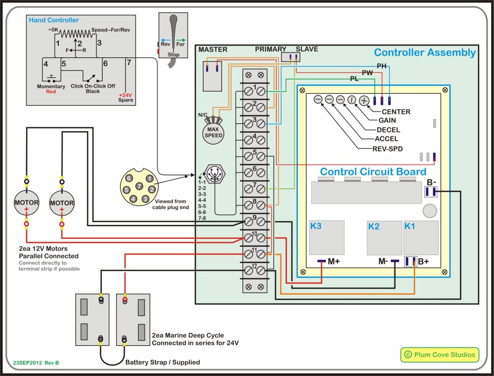
The drawing below is my reproduction of the schematic that comes with the Plum Cove controller. The P/C version was very difficult to read, so I decided to redraw it. I enjoy doing drawings, so why not. Plus, I added a few more details such as the guts of the hand controller, pinout for their 7 pin connector, the battery connections, and the motor connections. They have since made a change to the wiring, but I cannot find my original Corel file in order to make the change. :-(
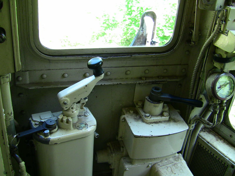
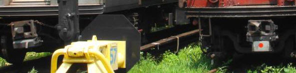
Eventually, I would like to duplicate this set-up below on the riding car. The throttle and -removable- reverse lever is on the left, the brake stand is on the right. The dead man control is incorporated into the throttle control, and if you notice, it is in the "up" position, and must be kept in the "down" position to operate. I believe (but not 100% sure), that it is a standard 8 position throttle, where the 1st four are parallel connections and the high speed (2nd four) are series connections. I also have to check, but they might be the series resistors your looking at on the side of the car, in white, between the two air tanks.
the Frame
I plan on using 3/4" square tubing, covered with a sheet of 063. I was originally going to use a sheet of 3/4" plywood, but I think that over a span of 8 feet, it would allow the frame to twist somewhat, which we don't want. I enjoy working with wood, only because it is easier to machine, and more foregiving of mistakes :-) The total thickness of the frame would be less than the 9 scale inches I have on the bottom of the car body, between the bottom of the body to the bottom of the doors.
the Body
Well, after much thought , consideration, and inputs from the guys on the Yahoo Live Diesel group, I've decided to make the body out of 0.063" thick sheet steel (commonly referred to as "O-63, just as Lionel stuff is called "O-27"). I found it at a local supplier for $102 a sheet. I figure I will use two sheets, and as a bonus, they will sheer it for free.
For the roof, we will (probably) make it in 2 or 3 sections, so it can be opened via hinges, and access can be had to various internal parts without opening the entire roof. Haven't figured out how to make the cooling vents yet.... Probably 3D them?
We have already picked up things like the horn castings and brake "pads" at the Cabin Fever Expo in Pennsylvania on previous visits.
Right now, I plan on making the doors operable, probably using R/C servos. I was thinking of maybe using an Arduino to control them and provide position memory, but I usually subscribe to the KISS principle, so probably not - but we'll keep the option open. The default on power up would be closed. If I do use an R/C servo, I would probably take the position feedback pot and rotation stops out, and that way, the motor can run continuously. If I connect the output shaft to say, a 6-32 all thread rod, I can use it to drive one door. Using a pair of gears, I can reverse a second shaft to move the other door of each pair in the opposite direction. I can solder two nuts to the top of each door to ride on the 6-32 shafts, which would also add lateral stability as the doors open and close. At the bottom of the doors, I can something like a small piece of brass angle to keep the doors from flipping out as the threaded rods rotate. A pair of IR LED emitters and receivers would be employed to report whether the doors are open, closed, or in between, so all you would have to do is press a button to open or close the doors, and the rest would be automatic. A separate set of controls would be needed for each side. I looked into using Actuonix linear actuators, but at 80 bucks a pop (or more, plus the control board(s) if used ($40 ea)), six of them would get pretty expensive just to open the doors.
Windows will be Plexiglas, we will try to find a small rubber or silicon "tubing" or such, and slit it so we can use it to mount the windows in place, like real ones are. We've decided on making the windows square in order to make fabrication easier, altho the window rubber will probably have it easier with rounded corners, another stay tuned.
Some of the stuff hanging off the bottom of the chassis:
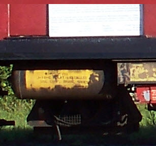
- Air tanks could be turned from nylon or something similar on a lathe.....
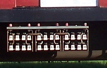
- The regenerative braking resistors (the things with the white ends) could be made out of balsa wood or styrene.....
- Other small detail parts could be made from brass or tin plated steel made for modeling.....
 -
-
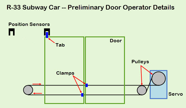
Doors
Right now, I plan on making the doors operable, probably using R/C servos. I was thinking of maybe using an Arduino to control them and provide position memory, but I usually subscribe to the KISS principle, so probably not - but we'll keep the option open. The default on power up would be closed. If I do use an R/C servo, the 360 degree rotation type would be best suited, maybe? I would probably use a pulley on the output shaft, then run some cord to two small pulleys on either side of the doors, which I could then have a clamp on each door, clamp onto the cord. Since there would be two cords behind the doors, one going in each direction, it would be easy peasy to clamp each door to one of the two cords so they operate in opposite directions. A single cord could be run behind all three doors on one side, alleviating the need to put a separate servo on each of the 6 doors, or not. The sensors and servo would be connected to an Arduino Uno to control the door operation: rate/speed (how fast the doors open and close) and limits so the doors don't open too far, or bang into each other when they close.
the Couplers
At first, I was going to use a plain old piece of flat steel to connect the subway car and the riding car. But after thinking about it for a while, I've decided to use standard working couplers on both ends of both cars. That way I can use the subway car remotely without a riding car. That will also require making some sort of provision for braking in the subway car, as I had planned on making the primary brake control in the riding car.
I may still make a prototypical coupler to put in the front pocket, just because.
The couplers I choose, only because they were easy to find when doing a search, are Railroad Warehouse part number RTRCP-02. They fit well into a standard pocket made from 1x2" rectangular stock.
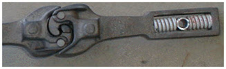
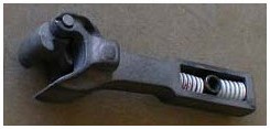
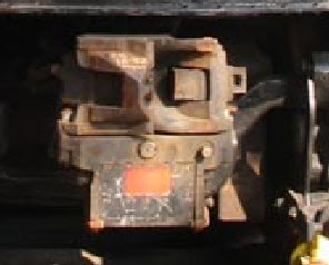
Actual couplers used on the cars. Not all NYCTA series used the same couplers, preventing mixing and matching. R33/R36 couplers are in the two left pictures.
Electrical - Low Voltage Section
This is my favorite part, the electrical section......
Batteries and In General
Headlights
Tail Lights
Marker Lamps
Express and Local Signs
Monitoring the Batteries
Batteries and In General
OK, let's start off with the low voltage section first. The drawing is a first draft, I'm still working on the details....
First up, the two deep cycle marine batteries, placed in series so we have a 24 volt system. We'll pull a center tap off of them for a 12 volt source to run those things which require 12V. This includes things like: 1) the headlights, 2) the marker lights, 3) the destination signs, 4) the Lo-V air compressor, 5) the Lo-V vacuum pump, 6) and the 120 volt inverter. We'll split the load as evenly as possible between the two batteries so one doesn't get overly discharged than the other. We need to move either the air compressor or vacuum pump to the other battery, in case we need vacuum brakes for any attached cars. The R-33 will use either regenerative braking or air released brakes.
To keep the batteries charged, I bought two battery chargers. Why am I using TWO battery chargers? Let's dive into some pseudo tech talk: While I -may- have been able to get by with one 24 volt charger, I'm taking the cautious route. Since I will be placing 12V accessories as loads on the two batteries, the discharge rate will most likely NOT be the same. So to charge the batteries, you need a different charging rate, or the same charging rate for a different length of time. So we don't have one battery less charged than the other, I will utilize two chargers. I know some of you reading this will disagree with me on this point, but for the piece of mind, and the minimal cost after everything else I have spent, another 50 bucks is trivial :-) Being particular about electrical and electronic stuff (some have called me anal, but that's OK :-), I want my batteries to last as long as possible, not only because they run around a 100 bucks apiece, but also because exchanging them and getting new ones is a major "PITA".
To explain a little more, let's say one discharges to 75%, and the other 60%. If I try to use one 24V battery to charge them up at the same time, one will be either overcharged or undercharged, while the other will be fully charged. You will never get both of them to be properly fully charged.
If we undercharge one, we won't get a full days running out of them, and, the undercharged battery could keep things from functioning properly because the voltage is low.
If we overcharge one of them, it unnecessarily overheats the battery, which could possibly buckle the lead plates, and shorten the battery's life.
Nether scenario is good. So that's why I plan on using two battery chargers.
In line with the batteries will be a switch/circuit breaker, this will make sure the power is really -off-.
On both ends of the subway car, I will be using 6 pin trailer connectors, two of them, for the electrical stuff. Maybe not particularly prototypical, but functional, and easy to replace if needed.
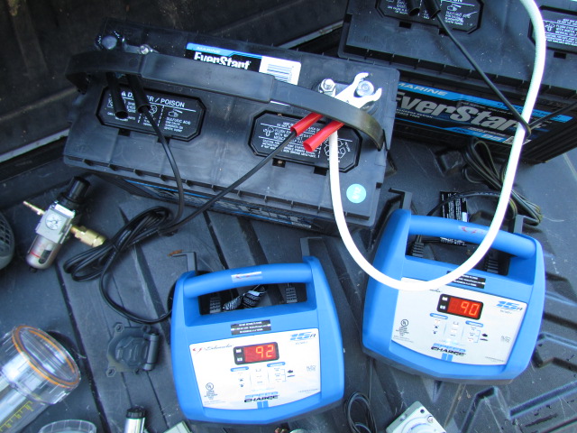
The photos below show the batteries on chargers sitting on the tailgate of my truck. One says 90 and the other says 92 - that refers to the percent of full charge on the batteries. When I'm running the subway car around, most of the time, it will be running off the batteries. As much as I try to equally load each battery, the load will never be the same, hence, the charge on the batteries will not be the same at the end of the day. These are Schumaker chargers, and I have decided against them, because if a battery falls below 6VDC, the charger will think it IS a 6V battery, and only charge it up to that voltage.... a serious flaw AND drawback!
Comments:
If anyone also happens to be into R/C models, you are probably familiar with the battery packs and chargers used to charge multi-cell batteries. The battery packs have a sense lead coming off of each cell so that the individual cells can all be properly charged, and that is why you can charge a 2, 3, or more cell pack at the same time with them all in series. The guys that do this in R/C modeling call this balancing, although because of the way the battery packs for R/C airplanes are made, the chargers can charge the individual cells properly. Using a standard 24V charger for our batteries, we do not have that luxury in the great majority of chargers, so they will not get a "balanced charge".
Someone commented that there is a 24V charger than can accommodate the differences in charge, but I'm not familiar with "it", and don't know how much it costs. These chargers are 50 bucks each, and will float charge the batteries once a full charge is reached. For the price, they do a lot, and have a lot of bells n whistles. Since originally writing this, you can now find smaller chargers, so I will probably opt for them :-)
If you decide to use gel-cel type batteries, you can not use this kind of charger, they will get overcharged.
Headlights
After much debate, I'm still looking around for a suitable LED, reflector, and lens to use for the headlights.
Being a subway car, they didn't use the "ditch light" function of alternating headlights, but I'm going to add that function using a 555 timer chip, easy stuff. The Baltimore LRV's (Light Rail Vehicles) have a push button switch on the console that activates this function when approaching a grade crossing or coming into a station. At least on the LRV's, they are not connected to the horn as they are on railroad locomotives.
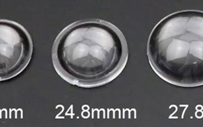
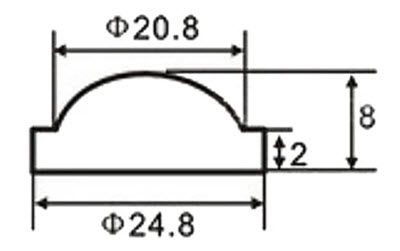
The hardest part is probably coming up with a suitable lens. Thanks to our friends in China, I may use some lenses I came across on Ali Express: 24.8mm diameter acrylic lenses. I've searched and searched and searched till I'm blue in the face, and have not come across one inch diameter Fresnel lenses, so my options are to make them or use non-Fresnel types. I could 3D print them, or use a "plain ole" lens and machine it down. Either way, it will take some doin.
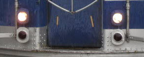
Headlights and taillights. I believe this and the picture below are from an R-36, which are almost identical to the R-33's.
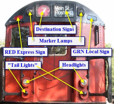
Location of lights on each end of the car.
Tail Lights
As for the taillights, they light up whenever the car is "auxed on", but the cab is not active (I don't know what they call "it" on these cars, but on the Baltimore LRV's, that's what it's referred to). When the operator enters the cab, and activates the controls, the headlights come on, and the taillights go off... pretty standard operating procedure for most transit vehicles. High output red LED's will be used for them. I will probably look for some 1/2 watters on EBay.
Marker Lamps
Subway cars also have markers lights, which can be one of several colors using glass filters on the real thing.
I plan on using an RGB (red-green-blue) LED. I will put two rotary switches in the front cab to control the left and right marker lights individually, with the lights at both ends being connected to the appropriate right and left markers. Again, LEDs are cheap anymore, even the RGB ones (or even an RGBW LED)! Probably one of the cheapest sources for colored LED's is either (after Christmas) multi-color LED light strings, or replacement LED's which you can typically find 6 or 8 for something like 50 cents (or less). I don't know how many colors the subway cars are capable of displaying, but the few assemblies I have seen on EBay, have 3 filters on a single assembly.
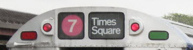 Destination and route number roll signs, marker lamps and express/local signs.
Express and Local Signs
Another cool feature of these subway cars are the express and local signs on each end. Over the operators cab is a red EXP, and on the opposite side is a green LOCAL sign. There will be a toggle switch in the front cab to control these signs, lit by red and green LED's. I could use either some plastic colored lenses I have laying around for Christmas lights, which would be easy to cut down and to shape, or, I have a bunch of theater type gels leftover from my days of "doing" lights in community theaters, and these would be super easy to trim down.
Monitoring the Batteries
While we're running around, we should be keeping an eye on the charge of the batteries. Since I started this page, there is a whole new world of "things" that can be used to accomplish this. Here are some of the options you have, these were all found on Ali Express. And be fore you down on me for using ALi Express, please tell me where you have the variety of options available to you from an American supplier. You can't. Another issue I read about on one of the Live Steam groups, is that one feller used a digital Chinese voltmeter, the thing shorted out, and burned out half his wiring. This could have been prevented by using a fuse in line with the meter. What's that saying - an once of prevention..... He said on his next iteration, he was going to use something "not made in China", but I'm not sure anyone in the U.S. manufacturers these kinds of things. Anyways, FUSE everything, like they do in your car..... it's an easy precaution. All of these were found on Ali Express searching with 12V DIGITAL METER.
 This one appears to have the most bells and whistles, and is around $15.
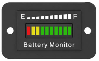 One of the most basic options, does not show you an exact voltage, but is quick to interpret.
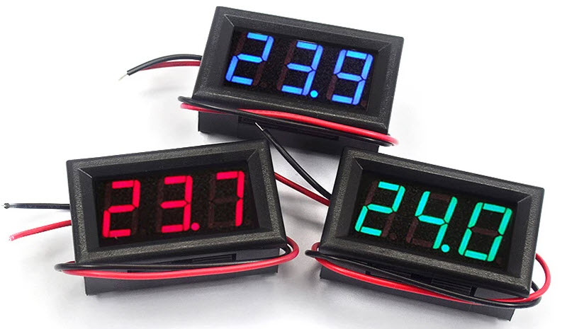 The most basic approach for voltage only, around $2 each, don't forget to fuse with a 1/4 amp fuse!
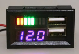 A slight upgrade from the basic meter above, with a couple of USB outlets, ~$2-3.
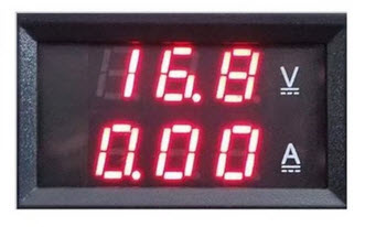 A basic
meter with both voltage and current displays, needs an external shunt, about 3 bucks.
A basic
meter with both voltage and current displays, needs an external shunt, about 3 bucks.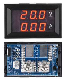 A combo meter with a built in shunt, I would probably shy away from this because of the shunt being built in.
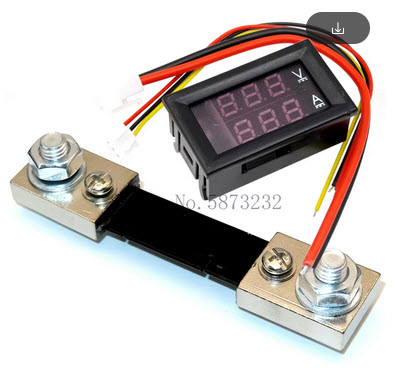 A combo
meter showing the external shunt provided with the meter, ~$4-5.
A combo
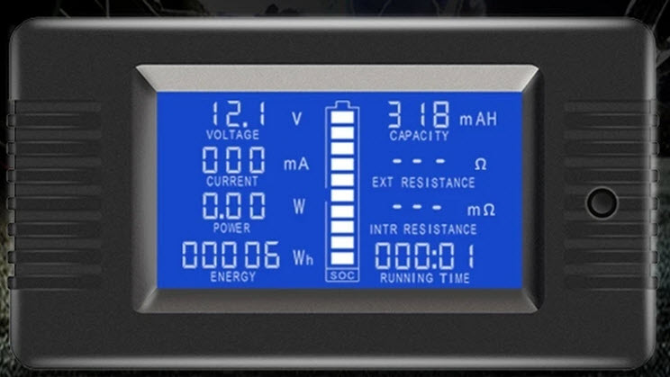
meter showing the external shunt provided with the meter, ~$4-5.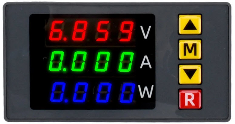 This meter also shows wattage, and has adjustable alarm set points, requires an external shunt, about 5 bucks.
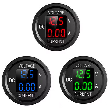 Round meters are easier to mount on a panel, here you have 3 color choices.
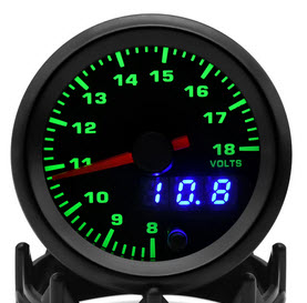
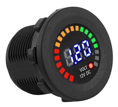 Two more round voltmeter only options! ~$3-6.
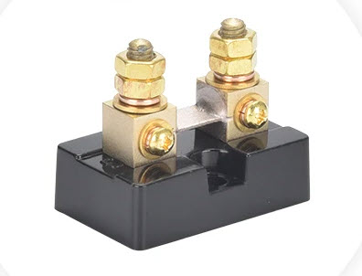 This is what a typical current shunt looks like, used with meters that need an external shunt.
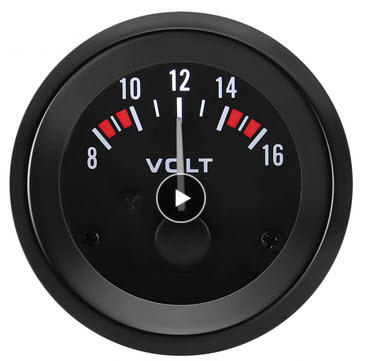 If you prefer, you can still go the analog meter route.
Electrical - High Voltage Section
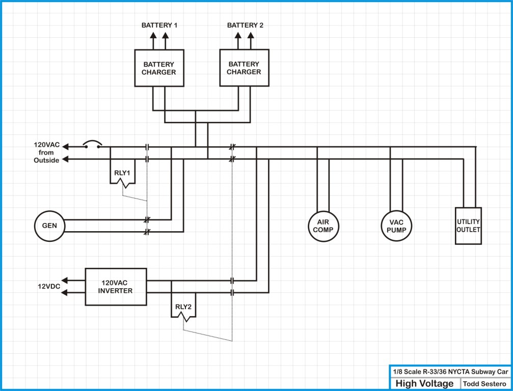
Let's start with the 120 volts coming in from the outside. It comes into the car via a DPDT relay (RLY1) and a circuit breaker or fuse. This is one of two relays used for isolation so the various A/C sources don't connect together and blow-up.
The other side of this first relay will get connected to the generator via the NC contacts. The 120 volt coil gets connected to the 120 volts coming in from the outside, so when it is not hooked to the outside source, the NC relay contacts will connect the load side to the generator. Plug the subway cars' cord into an extension cord, and the relay will pull-in, connecting the load side to the outside source.
The junction between the two relays is also where the battery chargers will get connected, for it is silly for the batteries to be charging themselves :-)
Relay 2 does the same for the inverter. Energize the AC inverter, the second relay will pull-in and disconnect the generator or outside AC source.
One of the other Harbor Freight things I got is one of their 800 watt generators so if I'm out on the track somewhere, and run out of anything, I can start that little puppy up and use the 120V stuff to recharge the batteries, air, or vacuum.
We're going to make this thing usable on both air and vacuum type braking systems. By adding a couple of extra valves, I can also make it so we can use either to APPLY the brakes, or RELEASE them. It's not very difficult to accomplish, and I'll go into detail below.
To supply the air, I plan on using two different compressors. One is a 12 volter from a car, like the ones Tom Bee uses. They were used to supply air for the air shocks on a wide variety of cars from Subaru's, Cadillac's and Dodge's. The second one is a pancake compressor that operates off of 120 VAC.
Most steam railroads use vacuum brakes, because it is easier to get via a steam injector as opposed to having a separate vacuum pump. So, in order to be able to use it on steam tracks, I bought a 120VAC vacuum pump from Harbor Freight. I found one that works on 12VDC in the scrap pile at work, used to irrigate infections or something like that - cool unit actually.
I plan on having 3 air lines going between the riding car and the subway car, so I can control the air and vacuum from it. The passthru to the following cars will have their choice of air or vacuum, either to apply brakes or to release them. I will probably use standard brass air tool quick disconnects between the riding car and the subway car.
I haven't yet decided what to do about the brakes yet. For testing purposes, without anything else hooked up, I guess I can use the regenerative breaking provided by the motors.
Whatever I decide on, I will most likely use air to release the brakes.
My options are:
-- Build custom disc brakes. It would probably be very easy to use the material below against a small disc placed on the axles.
-- To make my own brake shoes similar to what's available commercially.
-- To use the miniature brass or steel brake shoes available from several vendors on the internet. The steel ones are about 10 bucks apiece, the brass ones about $15. The brass ones have better "sticktion". I did buy a handful of brass brake shoes from a vendor at the Cabin Fever Expo.
-- I could also reline either of the above with a friction material available from McMaster-Carr Catalog page: click here
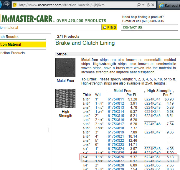
Comments from Chuck H about the stuff: Since my shoes were 1.5” long I purchased #6175K826 which is a 0.250” thick,
Below are a couple of shots of Tom Bee's braking system, which mounts into his truck frames. He uses his own custom made double acting pistons.
• Chains - Some clubs want 'em, so we'll put them on there.... one of the easiest things to add.
• Windows - Will probably be made from Plexiglas, fortunately, I can make it a tad easier by modeling the original version with square windows. The difficult thing to figure out the best way to make an acceptable looking rubber.
• Small lamp details and stuff like horns - These kinds of things could be done in wood, brass, steel, plastic, or 3D print..... dunno yet, details to be worked out. Once painted, you'll never know. I have found some acceptable looking horns at the Cabin Fever Expo held in Lebanon PA in the January time frame. If you've never been, you should!
• Doors - Being a subway car, I also plan on having operating doors. I will probably use airplane R/C servos, modified as mentioned below. Switches to operate the doors will be on the riding car controller, as well as push button switches in the leading end operators cab.
• Rolls Signs - We also need working roll signs too. I will use paper and modified small R/C servos to animate them. Paper is easy to print on once they are designed using Corel Draw. When I say modified, I bypass the R/C control part of the servo, and just use it as a motor! The switch to operate the roll signs will be in the leading end cab. Even tho this is planed as a #7 IRT car, I might make a roll sign for the line number too, maybe....
• Horn - Since no-one makes a sound board for these things, I guess I will have to put an air horn on it, or figure out how to make one that sounds like the original.....
Tools
I know people make a whole lotta fun about people who have and use Harbor Freight stuff, but for occasional use, most of their stuff works fine. I have one of their 9x20 lathes, mill, bender, cutter, etc, etc. Since I originally did this page, we have acquired a lot of Home Depot and Lowe's tools, and Ryobi powered tools.
I have a MIG and stick welder which can do the steel stuff with, and a buddy of mine has a TIG welder if I chose to use aluminum. CAUTION: A note about Harbor Freight TIG welders - they say they can be used on aluminum, but they probably shouldn't because every reference I've read on TIG welding says the current needs to be AC, and not DC, and ALL of the HF TIG welders have only a DC output! Buyer beware.
the Body
I'll probably use 3/4" plywood, stiffened by the sides, also made out of 3/4 ply. The edge will probably get painted white, while the deck of the car will probably get covered with a blue rug I originally got to cover my DJ console. The nice thing about it, is that is outdoor carpeting, and will kinda match the blue color of the car.
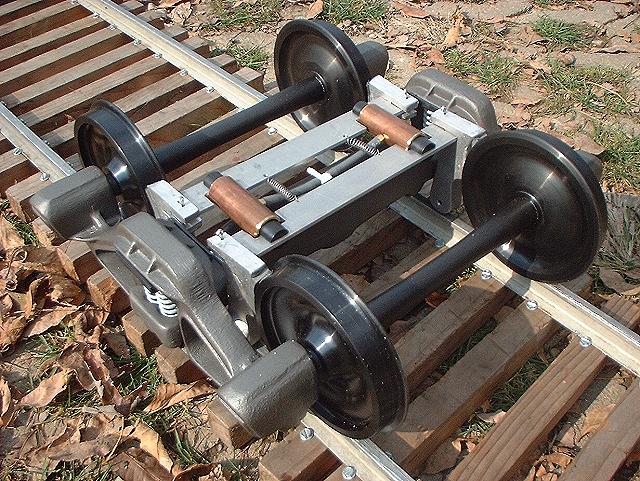
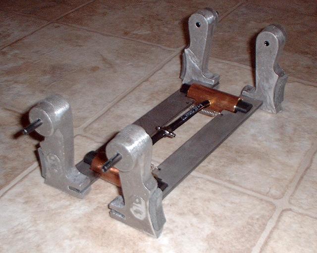
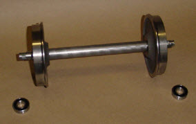
the Trucks
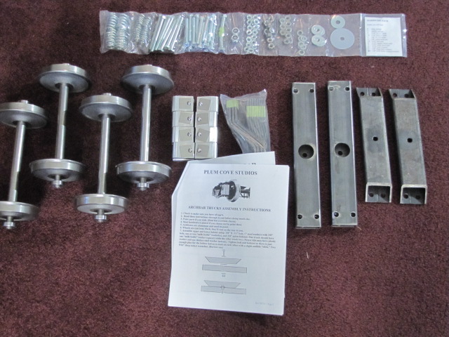
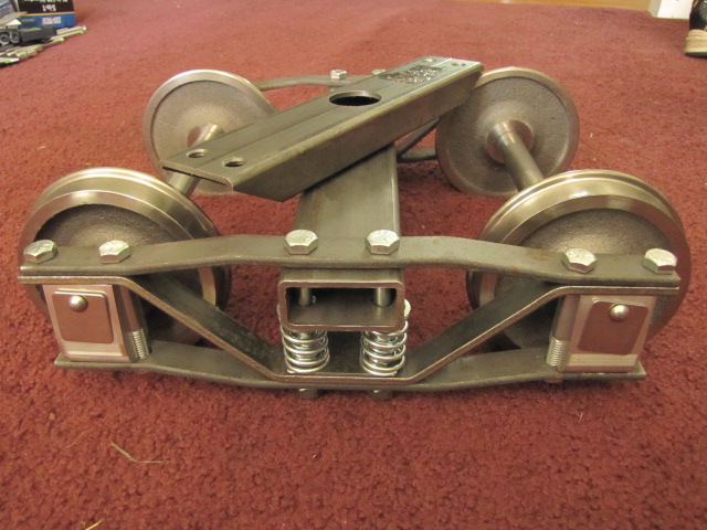
Staying with Plum Cove, I opted to use their arch bar trucks. Dunno why, I just like em. Before and after pictures are below. Sam does a nice job of packing the hardware so stuff is easy to locate. The assembly instructions are easy to follow, and assembly is a piece of cake! It took me about 30 minutes to put the first one together, and half of that was spent on several trips to the basement to get the tools I needed. The only thing you need to supply besides the tools is anti-seize so the bearings don't fuse with the aluminum pockets.

Costs
Everyone wants to know what a project like this costs, so here we go:
• $1600 - powered truck from Plum Cove Studios, includes two powered axles, frame, bearings, power controller
• $410 - non-powered truck from Plum Cove
$2010
• $399 - pair of arch bar trucks from Plum Cove
$2409
• $78 - pair of operating couplers from the Railroad Warehouse
$2487
• $175 - pair of 25R deep-cycle marine batteries from Walmart
$2662
• $18 - pair of plastic battery boxes - Walmart
$2680
• $100 - pair of Schumacher Marine type battery chargers from Walmart
$2780
• $40 - 4 flashlights to use as the headlights
$2820
• $35 - 4x8 sheet of plywood, 3/4", 7 ply
$2855
• $30 - 3 rotating boat seat bases
$2885
• $30 - 2 boat seat stands
$2915
An Interesting Comparison
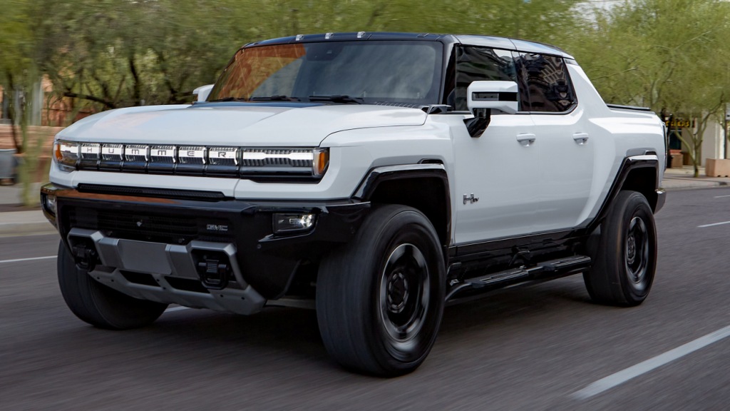
This -section- could not be written until 2022, when GMC introduced the Hummer EV to the world. This electric truck, with the 3 motor version, puts out an astounding 1000 horsepower! Compare that with the four motors the R-33 has at 100 HP each. The R-33 weighs 75,122 pounds (~37.5 tons), the Hummer weighs 9,600 pounds, less than the weight of a single R-33 truck (16,000 lbs). The batteries alone weigh around 3,000 pounds. The display software was written by a gaming company, according to the salesman. Also according to the salesguy, the Hummer appeals to doctors, as he said he sells a lot of them to doctors!
So, 75,000 pounds divided by 400HP gives us roughly [188] pounds per horsepower. The Hummer on the other hand, gives us [9.6] pounds per horsepower. Now you can understand why the Hummer can accelerate 0 to 60 in something like 3.3 seconds, which is claimed to be faster than the Corvette Stingray! For comparison, the 53 ton Baltimore LRV's have four motors with a combined horsepower of 1,100 (4x 275HP), which gives us [~96] pounds per HP.
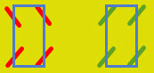
BTW, if you haven't driven the Hummer EV, you have to go to a GMC dealer and take one for a test drive! The thing is just impressive as you-know-what. You put that thing in the "WTF" mode with a full charge, and you're taking off like a rocket! WTF does not stand for what you think it does, it stands for "watts to freedom", but I believe they chose the name as a tidbit of humor :-) The truck can also do a few tricks no other car or truck can, and that is the "crab walk", where both the front and rear tires turn in the same direction, and you can drive sideways (in green below), or, the front and rear can turn opposite from each other, and you can turn the thing in a much smaller radius (in red). Things I guess that could come in handy if you're off-roading.
I have two criticisms: 1) the front hood release should be a purely mechanical mechanism as it is in just about every other vehicle. Why do I say this? I was reading about one driver's experience about his new Hummer, a fellow that does car reviews for a living, and his truck stopped dead in the middle of the road, and couldn't do jack-shit with it. He called up his son because he was at home in front of a computer and could look around for some answers as to what to do. His son said try disconnecting the 12 volt battery to reboot the main computer. The only problem was: the release function was computer driven, and with the computer misbehaving, that wasn't ever going to happen. He eventually found out that there was a manual pull release under the dashboard, but it was only a small little loop of wire, and was a pain-in-the-you-know-what tol on. A mechanical release would have been a simpler and more reliable option. KISS - keep it simple stupid. 2) The keyless entry and locking of the doors was not as simple as a my Ford King Ranch or Toyota Tundra. I don't remember all the details, but unlike the Ford or Toyota, if I remember correctly, you had to punch the unlock button on the keyfob before the doors would unlock, whereas on the other two, you just touch the handle and go - for both locking and unlocking..... you can keep the keyfob in your pocket. Bad decision Detroit!!!
If I had bought the Hummer, I'm sure I would have discovered a whole slew of other issues that make owning any vehicle "less fun", and after a while - things that really start gnawing away at you. I traded in a Honda SUV after only owning it for a year, because the thing, when you stepped on the gas, would sit there for something like half a second before the computer decided to do anything, and if you have a car barreling down on you and you need to get the f--k out of the way, you're screwed. I took it into the Honda shop, and the service manger said he couldn't reflash the computer, because there was no service advisory out on the problem... so, I traded it in on the Kind Ranch, and never regretted losing 10 grand on the Honda - that decision could maybe have saved my life :-)
Disclaimers:
New format 10/26/23: Please check out my disclaimer page for my standard dribble and contact info here
RAILFAN GUIDES HOME
RAILROAD SIGNALS HOME
NEW 08/25/2012, MAR11/2017, FEB25/2023, AUG25/26/27/28/2024
Last Modified 28-Aug-2024